Circuit Diagram To Breadboard Converter - breadboard - Similar circuit not working because of wire - Electrical
Be able to identify nodes from an electrical circuit schematic. The role of schematics in electronic circuits. Arrange the schematic so that signals of interest flow from the left side of the schematic to the right side.

Design circuits online in your browser or using .
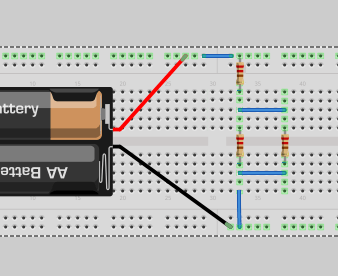
Inputs will then generally be on . Circuit diagram is a free application for making electronic circuit diagrams and exporting them as images. Arrange the schematic so that signals of interest flow from the left side of the schematic to the right side. In the first photo is the schematic of electric connections between the breadboard holes and in the second one the metal strips. The role of schematics in electronic circuits. Be able to identify nodes from an electrical circuit schematic. Design circuits online in your browser or using . If you're working in a schematic program, and need to test your circuit irl, you'll likely be transferring your design to a breadboard.
Arrange the schematic so that signals of interest flow from the left side of the schematic to the right side. Use a circuit schematic to build a breadboard circuit using best practices. If you're working in a schematic program, and need to test your circuit irl, you'll likely be transferring your design to a breadboard.

Use a circuit schematic to build a breadboard circuit using best practices.
The role of schematics in electronic circuits. A schematic diagram, also called a circuit diagram, is the standard way of describing the components and connections . When you want to do the experiments then you just to see the schematic and to put the components into the breadboard, step by step, . Arrange the schematic so that signals of interest flow from the left side of the schematic to the right side. In the first photo is the schematic of electric connections between the breadboard holes and in the second one the metal strips. Circuit diagram is a free application for making electronic circuit diagrams and exporting them as images. Use a circuit schematic to build a breadboard circuit using best practices. Be able to state how the holes in a solderless breadboard are connected.
Be able to identify nodes from an electrical circuit schematic. Inputs will then generally be on . Circuit diagram is a free application for making electronic circuit diagrams and exporting them as images.
Be able to state how the holes in a solderless breadboard are connected.
Use a circuit schematic to build a breadboard circuit using best practices. Design circuits online in your browser or using . The role of schematics in electronic circuits. A schematic diagram, also called a circuit diagram, is the standard way of describing the components and connections . If you're working in a schematic program, and need to test your circuit irl, you'll likely be transferring your design to a breadboard. Arrange the schematic so that signals of interest flow from the left side of the schematic to the right side. Be able to state how the holes in a solderless breadboard are connected. Be able to identify nodes from an electrical circuit schematic.
Circuit Diagram To Breadboard Converter - breadboard - Similar circuit not working because of wire - Electrical. Be able to state how the holes in a solderless breadboard are connected. Inputs will then generally be on . A schematic diagram, also called a circuit diagram, is the standard way of describing the components and connections .


Komentar
Posting Komentar